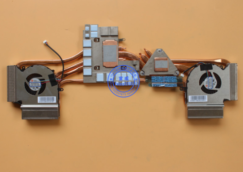
This is a picture of my style MSI heatsink with the factory "Gorilla Snot" on the GPU plate. Your only filling a roughly .5 gap. Not all components are running at the same temps and if you have them joined with paste or pad strips, the heat will transfer to the other cooler component before it will to the heatsink. They didnt cast those pad bosses separately to save weight! On my 2019 GL63 1660Ti plate I used .05 Thermalrite Odyssey 12.8 wk pads, cut separately, to replace the paste and .10 for the CPU strips. http://soft-matter.seas.harvard.edu/index.php/Eutectic_Gallium-Indium_(EGaIn):_A_Liquid_Metal_Alloy_for_the_Formation_of_Stable_Structures_in_Microchannels_at_Room_Temperature
So much easier to work on and clean up on the heatsink side. My foam is "fit" and epoxied "level" to the heatsink aluminium plates, with any overhanging foam epoxy painted on the top, plate side to stiffen it. The bottom is a flush compression fit to the nice and flat CPU plate "Up Above"
FYI: Yes! you can get NICKEL plating solution.$60 a quart. You can make a gallon of your own for $15. Same procedure and results as doing a car bumper but only doing small areas by brush instead of "Tanking"! Watch it on YouTube.
Just remember the proper PREP instructions and CAUTIONS! READ the MSDS.
CHECK temperature ratings of epoxys or ask the Seller.
The BE$$$$$T:
"Follow The Yellow Brick Road" https://www.liquidmetalalloy.com/about-us "Guess Who"
-
Attached Files:
Last edited: Jun 13, 2021 -
-
I'm just putting a reference here if anyone needs foam. I bought the 1/8" thick pads from here. I've ordered the 30ppi and 60ppi pads.
air filters | McMaster-Carr
Will give it a try on my Matebook X Pro and later on my Legion 7.Last edited: Apr 18, 2021Papusan likes this. -
Same Site, Different Flavor!!
https://www.mcmaster.com/foam/flame-retardant-super-cushioning-polyurethane-foam-sheets-and-strips/
Your post is Filter which allows pass thru. This stuff is Open Cell which will absorb a spill.(First item in list).
FYI: The generic Open Cell,1/8 packing sheet foam I used has shown no melting nor has there been any smells indicating any type of failure.Nor has the 5 minute epoxy I used for stiffening any foam overhangs and attaching foam to the coldplate.Last edited: Apr 23, 2021 -
If I'm not mistaken the foam air filters are also open-cell foam? As far as I am aware there is only open and closed-cell foam. The absorption of open-cell foam is determined by the ppi. Depending on how thick the foam is, which will determine what ppi is needed(say 60ppi for 1/8" foam), it won't really matter much since the foam will be highly compressed underneath the heatsink. The compression of the foam, which effectively increases the ppi in the constrained space, will effectively make the foam impermeable to liquid metal.Last edited: Apr 23, 2021
-
Absolutely! Could even use those 600 degree silicon O rings used in afterburner controls.Pointless when any old chunk of foam will do provided its installed properly.
edit: my generic packing foam was just a little crispy after 4 months but still serving its purpose.
Main thing is the proper application of the LM to the heatsink button with die-button contact patch matching. Has anyone done a test of two LM joined surfaces eg: taped together glass and copper plates.Introduce a massive shock and timed how long it takes for the stressed LM to go from liquid flowing state, back to its Gallium Oxide coated "in the bag" state after it escapes the plates? IF it escapes the plates!! them having straight ,flush edges.
MSI Intel i7- 8-9-10 series CPUs are usually factory set @ 95c PROCHOT. Using Throtllestop/Options set PROCHOT offset 3 points to more reasonable 98c before making any other adjustments. (99-100 for the mad men) MSI spec 95c Intel spec 100c
Using CLU LM on GPU-CPU Odyssey 12wmk pads and this small change my 3+ month old 2019 GL63 rarely exceeds 68c GPU or 87c except momentarily to 90-92c CPU while the power program figures it out.This is Ultra Gaming and Handbrake Encoding 1080 264 to 720 265 4 to 10 hours at a time. Runs 6 cores 3.3-3.4 average @ 85-87c max encoding,depending file types. Stock this thing had a near Full Red board on HWinfo and the CPU fan literally screeching and trying to escape out the corner.
Im to old to be Benchmarking the crap out of an Entertainment machine so it all works for me.Oh yeah! Fresh 10 Home- Battery set to 60% max charge using RWeverything program, power "Balanced" and $19 pre owned 230 watt HP power brick.What charges quicker when the power program sucks that "boost" from the battery? 180 or 230?
KISS https://www.reddit.com/r/MSILaptops/comments/jf0bwx/adjusting_battery_charge_level_without_dragon/
DONT BUY FOAM OF A CERTAIN THICKNESS just cause someone else says thats the answer.Required thickness varies between puters, vid cards and chip die heights. Put your heatsink on dry and make the measurement. Add enough to this to have a mild but firm compression on assembly. Your not containing an explosion!!Attached Files:
Last edited: Sep 17, 2021SierraFan07 likes this. -
-
Sorry if anyone has already posted something like this. I was wondering why these ultra thin 0.3mm thermal pads wouldn't work? Too much compression required maybe? I'm talking about usage in an MSI GE76 laptop which, unfortunately, does use tripod heatsinks.
https://www.amazon.com/gp/product/B...title_huc_1?ie=UTF8&psc=1&smid=A15YNZR7YB053N -
You do not want anything higher than a shore rating of 05 OO to interfere with contact pressure like this.
You have a few more options on LGA chips.FrozenLord and Papusan like this. -
Ok thank you. I don't know anything about shore ratings but I do see these are 80 OO which deduction would tell me is much too high. I'll stick with one of the million foam recommendations I've seen thus far lol.
Sent from my SM-G970U using TapatalkPapusan likes this. -
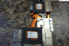
I have a GE76 and I'm getting ready to do LM. I saw your post above with thermal pad on the VRMS and other stuff but the latest pic they aren't there. Do you recommend thermal pads? Mine came with I think a liquid thermal pad, white and like marshmallow consistency so I wasn't sure what I'm supposed to put back in it's place. I noticed all the bigger chips seem to make direct contact with the heatsink so I don't see how I could use a thermal pad, but the little tiny ones have a gap and I put a 1mm pad on there as a test(after cleaning all the original crap off first) and it fit perfect. The first picture is where I plan on putting the thermal pads with the remaining parts using thermal paste, the second picture is showing test placement of thermal pad, the third just showing after I pulled off the heatsink after test placement, and the last showing the original product they used on the VRMS/Chokes and such. Are you concerned with using epoxy because it's permanent? I have thermal glue, I'm just worried that if/when it comes time to replace the foam dams I won't be able to clean it all off. Is there another less permanent way to get the foam to stick?
![[IMG]](images/storyImages/a0c765b4c817594a11d1107efe621ea6.jpg)
![[IMG]](images/storyImages/7b40b43989a08d4305cb32b6cf9638ac.jpg)
![[IMG]](images/storyImages/c1acbd859127319e89b3b4f425e9d742.jpg)
![[IMG]](images/storyImages/c363ac0549f23fb2a3e06b27ff4153b8.jpg)
Sent from my SM-G970U using TapatalkLast edited: Aug 16, 2021 -
Sorry! Was off trying to get 1070 working in 980 hole. Yes! Use the good 12 rated Gelid or Thermalright pads.DO NOT try cleaning the "Gorilla Snot" with iso or acetone.Take a tooth pick an roll it into balls and pick them off.Then wipe with a clean rag.I changed out the Epoxy mess for the 1/4 inch window sealer foam.The corners of which are sliced to 1/2 thickness and overlapped. Manufacturer recommends thermal pad thickness that JUST makes contact. They say compressing the pads too much lowers their ability to transfer heat?? Thats all fine but I wouldnt let it go to your head.Just a guide! Another of their hints is to use all .5mm thickness pads in questionable gaps and add another layer till you get that FIRM contact. Those Super Thin pads would be good here! Nickel Plated Heatsinks to avoid LiquidMetal absorption into copper heatsink and resulting "Drying Out"
Note" those larger chips DO NOT make direct contact to the sink.Put the Sink on dry and check the gaps as they will vary even in like machines. .05 pads worked for me.Last edited: Oct 3, 2021SamuelL421 likes this. -
Awesome thank you! I ended up getting non-hardening molding clay, placing it at about the thickness I estimated the thermal pads would need to be and then just seating the heatsink to determine if contact was being made and then adjusting pad height as needed after realizing there are small variances in height across the heatsink. I laughed when I saw you said you were down the rabbit hole of doing 980 to 1070 because that rabbit hole was what led me to getting a brand new laptop. I wanted to upgrade my 970 to 1070 on my 6 year old Clevo P770DM and during the time that I was searching to actually try to find a good 1070, the Tiger Lake refresh happened and I ended up going that route. Good luck in your endeavors!
Sent from my SM-G970U using Tapatalk -
Thanks! Bought a 2016 MSI GT72-6QE Dominator Pro 980m 4gb that spent 4 and a half years + in a pawnshop with a pooched V-card.Like New with the case protective stickers still on it. Just dusty!Last edited: Oct 2, 2021
-
That's awesome! I'm sure you are well aware then of the garbage 1070 mxm 3.x boards out there. I was told the ones manufactured by MSI/Clevo were the only ones worth trying to get your hands on.
Sent from my SM-G970U using Tapatalk -
Yep! Aware of the "Frankenstein" cards. Have MSI version 1.2. Just a heads up. There are a lot of posts on the threads that you require High heat sink pressure with Liquid Metal. That is the WORST thing you can do. It "fractures" the cohesion of the gallium (it has a Crystaline structure) at the highest pressure point even though its a liquid, flows to the low pressure surrounding areas,creates a dry spot and ZAP!! Stable with Matching Stencilled Contact Patches is the trick. I have an old 12 inch 3rd Gen HP Elitebook 2570p Quad Mod set up like that, nickel plated, with no dams,and have been tossing it around like a Beer coaster for a year with no ill effects and -20+ temps. So!Last edited: Oct 3, 2021Falkentyne and SierraFan07 like this.
-
Thank you, I don't know much about LM so I appreciate the input. I'm not sure I've done anything to increase contact pressure beyond how it comes from the factory. Mine has those springs inside the area where the screws are that go around the heatsink to prevent overtightening. The CPU has raised area on heatsink so pattern matching was a breeze there, and for GPU I cut some electrical tape to fit perfectly on the die, flipped it upside down, set the heatsink and then pulled it off, which now means the tape is stuck perfectly to the heatsink. I drew around the tape, removed it and then just applied LM inside the lines. I think another issue with my LM contact wasn't just the foam dams but not having enough applied. I was very cautious on first application but I know heatsink soaks in some of it and I just think I didn't have enough. I applied a little more the second time so I think that helped. In a perfect world I shouldn't barely need to apply any but the reality is I don't know how well my heatsink makes contact, coupled with a tripod design which may not make as good of contact as a quad design as well. I kick myself realizing I could have used my molding clay to get a good idea on how close the contact was between heatsink and dies, so if/when I repaste I will do that to get a much better idea on just what kind of contact is being made.
Sent from my SM-G970U using Tapatalk -
Yeah you don't want high mounting pressure. Just even flat mounting pressure is good enough. But you don't want LOW mounting pressure or Tripods either.
I've seen this phenomenon before. It can be avoided by performing a simple trick (as long as the mounting pressure is perfectly even!) ---wipe the heatsink/IHS and CPU die/surface with 1500 grit sandpaper to roughen it up first, fully clean it after, then apply LM, spend about 10 minutes wiping it around continuously in soft, even, circular strokes with a LINT FREE swab (lint free eyelash liners / lip gloss applicators works well, better than the Thermal Grizzly swabs, I use these: https://www.amazon.com/Applicators-Disposable-Brushes-Lipstick-Applicator/dp/B085XXXPMM ) ; if you feel any rough particles, you applied too much pressure), then after 10 minutes, apply a second small amount on top of the first and mount it. This way, since you roughened up the heatsink and the CPU core (I do both), the LM is able to work into little micro crevices and settle, having something to 'grip' to, rather than "pooling to itself". I've seen the "pool to itself' issue on a perfectly polished 9900k underside IHS, which is when I realized LM hates polished surfaces (and it was someone in the Clevo section who first mentioned that fact years ago).
I checked my MSI GT73VR heatsink yesterday after 2 years of a LM application. The CPU was still 1C core temp deltas (4C/8T) and the LM was almost completely pristine, with just a small hardened spot in a corner of the heatsink, but the main layer was fully liquid, so there were no dry spots anywhere. Two years. Reminds me of @Papusan 's results.Last edited: Aug 20, 2021FrozenLord, tilleroftheearth, SierraFan07 and 1 other person like this. -
Dude that's an awesome idea and makes logical sense! I think I'll try that next time around. I'm saving your info to my GE76 tips and tricks Word doc I created so I don't forget all the new stuff I'm learning
 Thank you again for your great feedback. I love learning and it's why I've always enjoyed this community.
**Edit: Two years later and having LM still look like that is incredible and another great reason why someone might consider using it over traditional pastes beyond just the thermal benefits.
Sent from my SM-G970U using Tapatalk -
Other than keeping nice sharp edged matching contact patches, the other biggie when using LM directly on copper is "tempering" the copper contact patch.Totally amazing just how fast the copper absorbs the LM. I scuff my heatsink with 400 grit wet and dry cloth soaked in acetone. Then a good washing with acetone and stiff brush. Stencil the matched contact patch and put on a "wet" even coat of LM ,working it into the pores of the copper, forcing trapped air out. Let that sit for a minimum 4-6 hours, preferably overnight. Wipe excess off before giving a light even coat before final assembly. In another one of my posts there is a pic of just how deep it sinks in. When prepping for nickel plating later, I had to use 80 grit to get down thru it. http://forum.notebookreview.com/threads/long-term-liquid-ultra-results.834821/page-4#post-11099681
Any roughing or scuffing of the CPU or GPU dies is an ABSOLUTE NOT! While referred to as the Die in general terms, that part of the CPU is in fact an "Oscillator" and that mirror like surface is there for a purpose. The ocillator changes the electrical functions generated heat in the processor into radiation which is radiated out thru "the looking glass" as it is the most efficient way to get the heat, thru the TIM to the heat sink. Suggesting sanding on the glass is like saying Cyanide will clear your throat. Good cleaning with Acetone and polish with lint free cloth and thats all. Most marring of the glass surfaces is plain laziness and failing to clean with a true evaporative like acetone from the git go!.I do not make wild statements without a hell of a lot of research!
There is no such thing as "pooling" when the heat sink is attached. There is the chance of dry spots from failing to "work" the LM on all CLEAN surfaces including the oscillator. Working it evenly removes air from the coppers "pores" and provides the Surface Tension required to hold a uniform coating. "POOLS" of Gallium are the reaction of air on the surface of the Gallium creating a coating of Gallium Oxide which forms a "Bag" containing the Gallium. This surrounding Bag effect combined with Surface Tension and your nice sharp,matching, stenciled contact patch edges keeps everything in place.I have no experience with delidding processors but it is not difficult to see that taking something apart that was not designed to be is going to be problematic. But then the wizards with Laser Tip fingers can no doubt fiqure that out.Last edited: Jan 18, 2022
Foam dam barriers for Liquid Metal safety insurance guide.
Discussion in 'Hardware Components and Aftermarket Upgrades' started by Falkentyne, May 21, 2018.